
Medium C’s
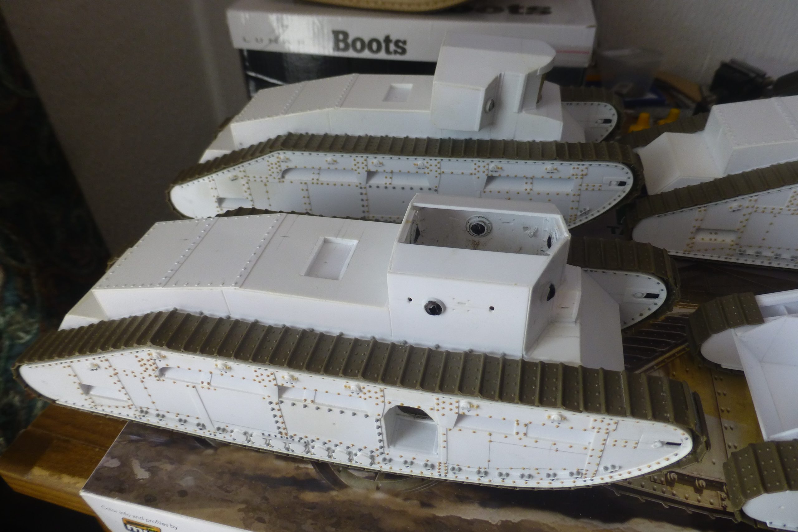
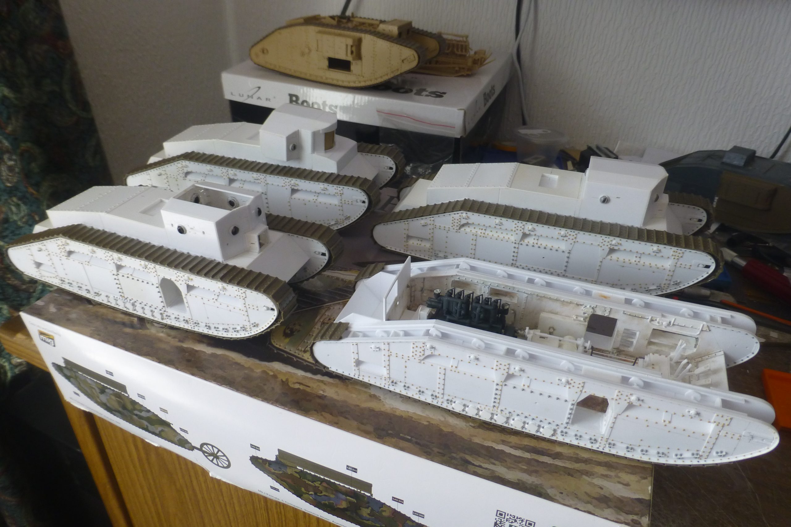
The original plan was to build 3 tanks in 1/35, Hornet from Fosters works, a standard female machine and 6pdr armed Male tank destroyer.
For references I used available photos (mainly from the IWM site) and the parts book drawings along with Fosters Hull & GA Drawing’s available from the Tank Museum.
The first issue was to get a true to 1/35 scale drawing printed from the available sources. This was achieved using image software and a bit of cheating the printer to print what I wanted not what it thought I wanted.
1 master hull side was created and this was replicated to give the 12 sides needed to produce 3 tanks.
All holes drilled from a common master side, spare wheels and track from spares in other kits, this resulted in 3 pair of track frames.
Centre section of the hull built between each pair of track frames leaving the cab roof till last.
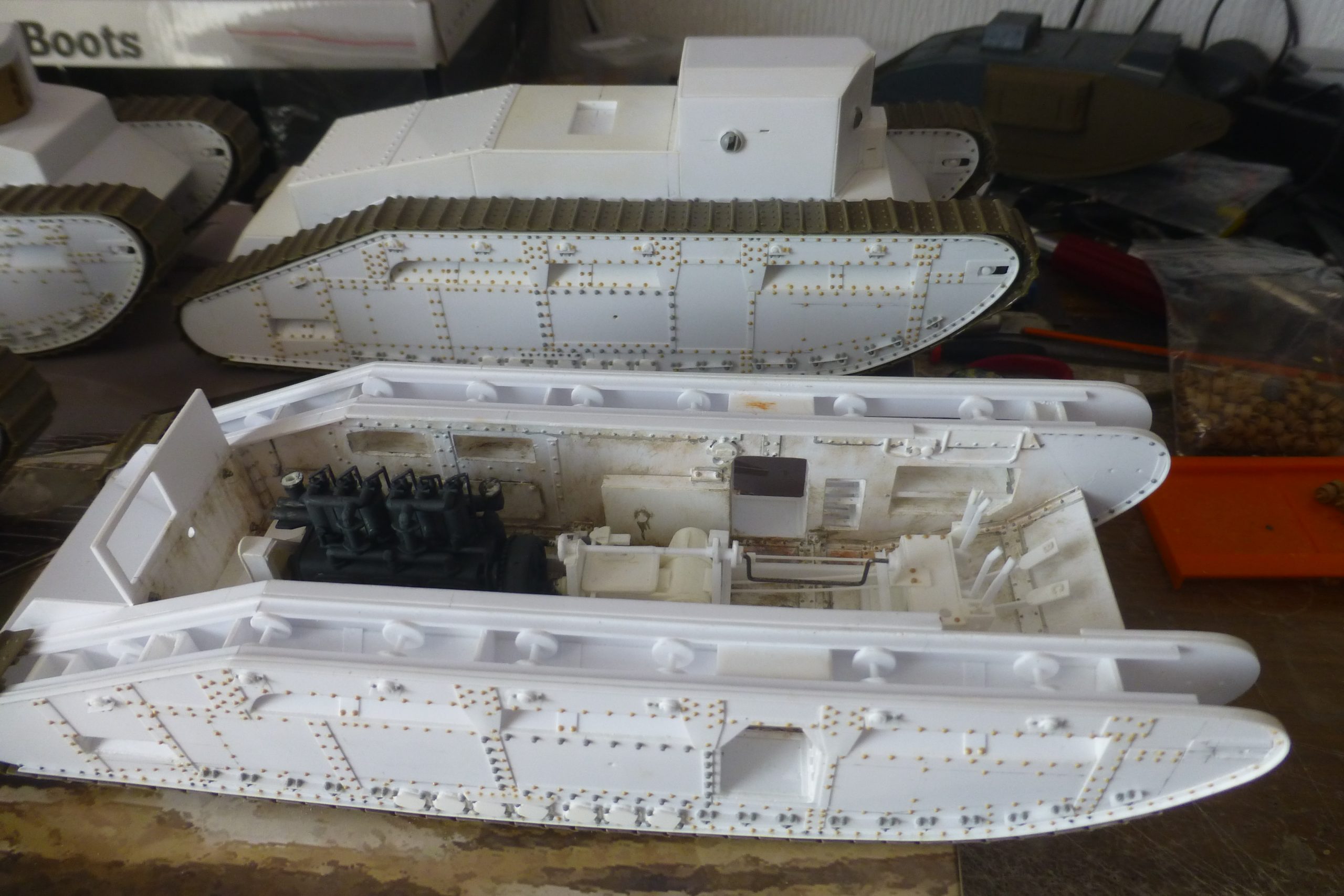
At this point I though it would be a good idea to build the standard tank with a hatch or two open.
The one photo of the interior of a C only shows the driver’s seat, so I took a good look at the GA (Foster’s drawing 850V (TM Ref 623.438.3)).
So, I decided that with a bit of work I could open up the hull side hatches and make an attempt at the interior forward of the radiator assembly. This worked out so well I thought why not make another tank but plan to build a full interior from scratch, the obvious choice for the model was from a photo of about a dozen of them waiting to be scrapped. This had the extra advantage that the engine deck had been modified in the 20’s to hinge opening on the left side, ideal to show the interior. I had kept progress on the first 3 at an equal stage to avoid one being left on the shelf for years, once I’d started on the 4th that got progressed until it had caught up with the others. Since then, I’ve tried to keep them all at the same stage, so build 4 sets of everything. The most recent item batch built was the brackets for the camouflage poles, five on each side of the tank, each bracket is made of 4 parts and 6 bolt heads.
Rivets, the best source I’ve found is the inner faces of the track frames used in the Mk I/IV kits, those rivets cut off cannot be seen once the track is put on the standard model and there are hundreds that can be removed from a single kit (and even some bolt heads) Most bolt heads come from the Meng sets which are a very cost-effective source.
Most models I’ve seen before of the Medium C have the cab sides being an equal length, the drawings and a quick rivet count clearly show this was not the case. Drawings and some weight details exist for the Male tank. The only bit that is not available is a rivet / hatch drawing for the roof panels. I used the same pitches as used on the joining strips for the Standard tank on the Male roof. The parts book shows the cupola was mounted on one of these joins, but which side? Having built the model complete which breech block etc it became obvious that the only place had to be near the back on the lefthand side, the MG mount also had to be considered.
IWM Film 1191 shows testing of 3 C’s at Lincoln, at Foster’s field just South of Wellington Works, along with a few seconds of the works itself. There are several C’s complete both inside and outside the hanger along with the 3 showing their paces. In the background on the South side of the field there also looks to be 5 or 6 part finished hulls without cabs. The works footage shows some machines in final stages of assembly along with a few Tadpole tail units. Was the Male tank ever built, possibly not to completion, but maybe the Manchester group started construction of some bare hulls, more research needed!
David Fletcher’s article on the Medium C many years ago in Army & Navy Modelworld was also a good source of information and was one of the first to include details of the Male tank.